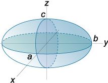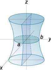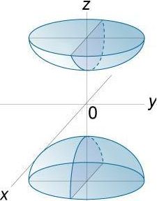
| plane | 3 |
| sphere | 4 |
| ellipsoid/ ellipt. hyperboloid | 6 |
| gen. quadric | 9 |
First of all, data points must be given, through which the surface should pass, perhaps only approximately. All those points must have three coordinates. These coordinates are specified via . In the right table the minimum number of data points is given for each type of surface. Some special configuations of data points may make the linear system of equations singular and are illegal.
As a first result for the desired surface you obtain the surface equation, from where you can derive the parameters of the surface defining its size, shape, position and attitude.
Plane: (vX, vY, vZ)T is a unit vector perpenticular to the plane (the so-called normal vector), which points away from the origin of the coordinate system. w>0 is the distance of the origin from the plane:
vX · X + vY · Y + vZ · Z = w
Sphere: Xo, Yo, Zo are the coordinates of the centre, R is the radius of the sphere:
(Xo - X)² + (Yo - Y)² + (Zo - Z)² = R²

Triaxial ellipsoid / elliptic hyperboloid: Xo, Yo, Zo are the coordinates of the centre of the figure. a,b,c > 0 are the parameters of form of the surface. For the ellipsoid, they are the semiaxes. Also for the elliptic hyperboloid they are sometimes called semiaxes. The axes and planes of symmetry pass through the centre and are situated parallel to the axes and coordinate planes:
| ± | (Xo - X)² | ± | (Yo - Y)² | ± | (Zo - Z)² | = 1 |
| a² | b² | c² |


The type of surface depends on the signs of the fractions in this equation:
General quadric: This type of surface is nothing but a triaxial ellipsoid or elliptic hyperboloid in oblique (non-axiparallel) attitude:
| =1 |
Xo, Yo, Zo are the coordinates of the centre of the figure. Everything else is determined by the eigenvalues and eigenvectors of the matrix factor U The signs of the eigenvalues determine the type of surface following the same rule as above. The semiaxes are the eigenvalues by the power of -0.5. The eigenvectors are parallel to the axes of the quadric.
If the number of data points exceeds the number of points required for the unique determination of the surface (redundancy, table then an adjustment is computed by the method of weighted least squares. In the case of the algebraic adjustment, the constants on the right hand side of the surface equations w, R² or 1 are treated as equal-weighted observations and are ''adjusted''. Possibly given standard deviations or weights are not used here.
In this case accuracy measures are required for the coordinates of the data points, either as standard deviations σ or as weights p. In the first case weights are computed by p=1/σ². Contrary to the algebraic adjustment, the stochastic adjustment treats the coordinates of the data points equipped with accuracy measures as observations. Coordinates without accuracy measures are treated as error-free and generate a constraint. If there are more error-free coordinates than surface parameters, the computation is impossible.
Optionally points can be given, which need to be projected onto each computed surface. The coordinates of these points are specified via . Type of system and column format must coincide with the settings for the data points. Two different modes are supported:
If the points to be projected are located far away from the data points, the accuracy of the projection is often poor due to the bad error propagation of the extrapolation.
It is possible that data points and points to be projected have equal names. This case will inevitably occur, if the column format ''coordinates'' is chosen. In order to avoid confusion, this option is not recommended.
In case of 3D points to be projected the point to be projected and the projected point in the surface have the same name. If this is undesired, a suffix may be appended to the names of the projected points to distinguish them from the names of the points to be projected.
On the canvas all data points and points to be projected as well as projected 2D and 3D points are displayed in horizontal projection. For each point only the last valid coordinate solution is displayed. If projected points have no suffix, the point to be projected are thus not displayed. In the column format '' coordinates some points will not appear on the canvas
is not yet possible at the moment. Please use cartesian instead.

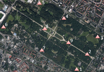
At Dresden Großer Garten the following terrain points are measured:
 East. [m] North. [m] Hght [m]
1 413736      5653962      122
2 414006      5654264      123
3 414145      5654626      117
4 413496      5654915      121
5 413035      5655364      114
6 412418      5654935      116
7 413134      5654353      121
8 413163      5654817      115
9 413678      5654471      121
Although these coordinates refer to the UTM zone 33U, we work with a cartesian system, as long as grid systems are not yet supported in . Due to the low accuracy of the horizontal coordinates, the grid scale factor can be neglected already here.
The mean surface slope is desired by computing an adjusting plane through these 9 points. On this plane lattice points with a lattice spacing 100 m × 100 m should be computed. (Tip: )
The resulting plane is described by the equation
0.0057072740260338 · X -0.00092455626269208 · Y + 0.99998328596978 · Z = 32009.200056141
from which you extract the slope angle:
arccos(0.999983286) = 0.331° = 19.9`
Moreover, you also extract the azimuth of the dip (steepest descent):
arctan(-0.000925/0.005707) = 350.8° = 389.8 gon
The dip is approximately in a northward direction.
also computes a plane through three points or a sphere through four points. Weights do not matter, they may also be omitted. If you need the distances of further points from the surface or their projections onto the surface, specify them as points to be projected . The distances are computed by the lengths of the difference vectors.
A different solution for the sphere through four points is obtained by and the quadrispheration by four pseudo ranges. The four points are specified as centres of four spheres with identical pseudo ranges, most easily with 0;0;0;0 The radius of the desired sphere is the obtained distance, which is identical four times. The centre of the desired sphere is the obtained intercept of the four spheres. The practical advantange of this method is that this centre can directly be transfered to coordinate list. (Computationally, one obtains two identical intercepts, one with ''negative'' radius of equal absolute value, which can be discarded.)
|
|
|
Ausgleichungslehrbücher |