
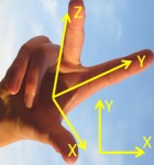
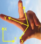
IN DUBIO PRO GEO computes planar and spatial coordinate transformations, i.e. conversions of point coordinates of an source system to coordinates of a target system. We do not require any special approximate alignment of the axes of the systems. Coordinates are specified via .
Cartesian lefthanded, cartesian righthanded systems (XYZ) and grid systems (northing,easting,height) (or other succession of coordinates) can by transformed immediately. Ellipsoidal systems (latitude,longitude,height) must first be converted with . See coordinate system type.
The coordinates in the source system are always denoted by x,y,z and in the target system by X,Y,Z . For grid coordinates we identify north = x and/or X, east = y and/or Y and height = z and/or Z.
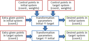
Control points are identified automatically by identical pointnames. Whenever possible, transformation parameters are computed from those coordinates.
Additionally, there may be points with coordinates given only in one of the systems (new points). The computed transformation is applied to them. There may be new points in both systems at the same time.
All points can be specified in the coordinate lists in arbitrary succession.
All implemented geodetic coordinate transformations are computed, which fulfill the following three conditions.
All transformations use the following template of a system of transformation equations :
| V = t + T · v | v , V are the position vectors of points in the source and target system. t is the translation vector (= shift vector). T is the transformation matrix. |
The succession of the components of v, V, t, T is always XYZ, even if the coordinates in the have a different succession. Depending on the type of transformation, Teffects
For each computed transformation all transformation equations are given in the above form, such that all additional computations can be performed, e.g. the transformation of additional points. Often it is appropriate to specify the transformation by transformation parameters. Unfortunately, there is a multitude of possibilities, how to do this, which are supported here almost completely:
It is easiest to represent T as a product of at most three matrices:
The different types of transformation differ with respect to the set of factors, which compose T , and their succession. For the affine transformation, T can be decomposed into all three factors in arbitrary succession:
T = Q1M1S1 = Q2S2M2 = M3S3Q3 = S4M4Q4
The factors themselves depend in general on the succession of the decomposition, e.g. you get S1 ≠ S2 ≠ S3 ≠ S4. All above-listed decompositions are computed.
Z coordinates or heights are not influenced by planar transformation, they may therefore be missing. If heights are given for some or all points in grid systems then they are used to determine the grid scale factor .
Whenever possible, the following transformations are computed one after the other:
| Transformation | Parameter | Number | Contr.P. | Transformation matrix T | |
|---|---|---|---|---|---|
| Affine | tx , ty , mx , my , ε , τ | 6 | ≥ 3 | is a general 2×2 matrix | |
| 5-Param. type 1 | tx , ty , mx , my , ε | 5 | ≥ 3 | has orthogonal row vectors | T=MQ |
| 5-Param. type 2 | tx , ty , m , τ , ε | 5 | ≥ 3 | T=mSQ | |
| 5-Param. type 3 | tx , ty , ε , mx , my | 5 | ≥ 3 | has orthogonal column vectors | T=QM |
| 5-Param. type 4 | tx , ty , m , ε , τ | 5 | ≥ 3 | T=mQS | |
| Helmert | tx , ty , m , ε | 4 | ≥ 2 | is the scalar multiple of an orthogonal matrix | T=mQ |
| with fixed scale | tx , ty , ε | 3 | ≥ 2 | is an orthogonal matrix | T=Q |
The translation vector t and the matrices Q, S, M have the following representation:
| t= |
|
without reflexion: |
Q = |
|
with reflexion: |
Q = |
|
| S = |
|
= |
|
M = |
|
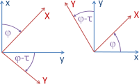
The rotation angle ε is the rotation angle from the source system to the target system about the origin. In the lefthanded system ε>0 means a clockwise rotation, in the righthanded system conversely.
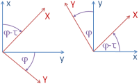
After a shear mapping, the axes of the source system do not enclose a right angle, but an angle diminished by the shear angle τ or enlarged by -τ . In the computation protocol the shear factor f = tan(τ) is also reported.
The scale factors mx , my are always positive and for some transformations of equal size. mx = my = m > 1 means that the points are pulled apart. The grid scale factors are not included. E.g., if you change the grid to cartesian, the scale factors may also change.
Three coordinates must be given for all points. If the transformation type auto-detect is chosen, then spatial transformations are computed whenever this condition is satisfied and the third coordinates of all points are not all identical. Otherwise, it is tried to compute planar transformations.
Whenever possible, the following transformations are computed one after the other:
| Transformation | Parameter | Number | Contr.P. | Transformation matrix T | |
|---|---|---|---|---|---|
| Affine | tx , ty , tz , mx , my , mz , εx , εy , εz , τxy , τxz , τyz | 12 | ≥ 4 | is a general 3×3 matrix | |
| 9-Param. Type 1 | tx , ty , tz , mx , my , mz , εx , εy , εz |
9 | ≥ 3 | has orthogonal row vectors | T=MQ |
| 9-Param. Type 2 | tx , ty , tz , εx , εy , εz , mx , my , mz |
9 | ≥ 3 | has orthogonal column vectors | T=QM |
| Helmert | tx , ty , tz , m , εx , εy , εz | 7 | ≥ 3 | is the scalar multiple of an orthogonal matrix | T=mQ |
| with fixed scale | tx , ty , tz , εx , εy , εz | 6 | ≥ 3 | is an orthogonal matrix | T=Q |
The translation vector t and the matrices S, M have the following representations:
| t= |
|
S = |
|
= |
|
M = |
|
The 3D shear mapping represented by S may be viewed as a sequence of three planar shear mappings, in particular
If one interchanges the 1st and 2nd or the 2nd and 3rd planar shear mapping, one approximately obtains the same shear angles τij, if they are small. In the computation protocol the shear factors fij = tan(τij) are also reported.
The 3D scaling has up to three scale factors. The two scale factors of planar transformations are completed by a 3rd scale factor mz .
The matrix Q is in the case without reflection a rotation matrix and can be represented by parameters in the following three different ways:
(a) with three Eulerian angles εx , εy , εz:
| Q= |
|
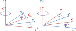
The total rotation can be viewed as a sequence of three rotations about coordinate axes. We use the geodetic convention:
There are alternative conventions in use, mainly in the non-geodetic branches.
(b) with the quadruple of the unit quaternion (q0 , q1 , q2 , q3):
| Q= |
|
A quaternion usually permits a more elegant description of rotations in three dimensions than Eulerian angles. The four parameters satisfy the condition q0²+q1²+q2²+q3²=1 (unit quaternion).
(c) with Eulerian axis (ex , ey , ez) as a unit vector and rotation angle ε about it:
| Q= |
|
The rotation is here described about an oblique axis through the origin of the coordinate system, the so-called Eulerian axis. The parameters satisfy the condition ex²+ey²+ez²=1 (unit vector).
All angles εx, εy, εz, ε are computed between -π = -180° = -200 gon and π = 180° = 200 gon in the chosen angle unit. They are defined
The viewing direction for this is opposite to the rotation axis. Negative rotation angles ε are avoided by reverting the Eulerian axis.
There are alternative conventions in use, mainly in the non-geodetic branches.
If the source system is a lefthanded system and the target system is a righthanded system or vice versa, T must additionally generate a reflexion . The indication of this is det(T)<0. We realize this by mirroring at the yz plane.

In this case it is assumed that the vertical axes (Z or height) of both systems are parallel and have the same scale. From all control points with three coordinates in both systems the vertical offset is computed. At least one such point must exist. This offset is used to transform all non-control points into the opposite system. To the other two coordinates all applicable planar transformations listed above are applied.
If the number of coordinates of control points exceeds the number of transformation parameters in a transformation (redundancy) then an adjustment is computed by the method of weighted least squares. In this case accuracy measures are required, either a standard deviation σ or a weight p . In the first case the weight is computed by p=1/σ². For this purpose two modes are implemented:
| Weight | Std | When computing the transformation parameters, the corresponding coordinate will be |
|---|---|---|
| 0 | INF | ignored. |
| INF or empty field | 0 or empty field | used as a constraint. |
After the adjustment there are often residuary misclosures. They coincide by magnitude to the residuals of least squares adjustment, but have the opposite sign:
residuary misclosure = given coordinate − coordinate computed from transformation parameters
Under the bonnet: Internally, IN DUBIO PRO GEO always works with the elements of t and T as adjustment parameters. For planar transformations we always get 6 parameters and for spatial transformations we get 12 parameters. For all non-affine transformations the restriction to special transformation matrices T is realised by restrictions for the elements of T . Only after the adjustment, scale, shear and rotation parameters are computed by QR or RQ decomposition of T In view of this, adjustment parameters and transformation parameters must be distinguished, except for the affine transformation.
If also transformation parameters of the reverse transformation are required, it is recommended to change the transformation direction by swapping the systems. Note that the parameters of the reverse transformation are not always obtained by reversing the signs of the angles and by inverting the scale factors.
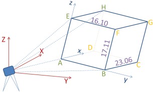
Four vertices A,B,E,H of a cuboid ABCDEFGH with edges not parallel to coordinate axes are measured by tacheometry (⇒ figure). With a standard deviation of 0.02 the following coordinates in the station system (cartesian lefthanded system) X,Y,Z are obtained therefrom:
    X        Y        Z
A   14.029   17.058    8.073
B   23.616   29.751    5.516
E   14.272   20.210   24.880
H   32.863    6.737   27.163
For all points C,D,F,G of the cuboid not sighted, the coordinates in the same system need to be determined.
   x  y  z
A  0  0  0
B  0  1  0
C  1  1  0
D  1  0  0
E  0  0  1
F  0  1  1
G  1  1  1
H  1  0  1
In addition to the station system xyz we introduce an object coordinate system xyz as displayed above as a cartesian lefthanded system with axes along the edges of the cuboid. However, the edge lengths are not known. (The values in the figure above represent the true solution.) So we take these lengths as units of the coordinate axes. In this way for each coordinate axis a different length unit is defined. Now we assign object coordinates to the points A…H. They are treated as error-free.
The spatial transformation from the object system to the station system must effect
Therefore, the appropriate transformation is a 9 parameter transformation type 2.
From these coordinates, only the affine transformation and the 9 parameter transformation type 2 can be reasonably computed. For the other transformations, the control points do not approximately match (large residuary misclosures).
The least squares method converged after 3 iterations.
| = |
|
+ |
| . |
|
| comp. | object system | station system | ||||
|---|---|---|---|---|---|---|
| points | x | y | z | X | Y | Z |
| A | 0 | 0 | 0 | 14.0401824 | 17.0409621 | 8.0693290 |
| B | 0 | 1 | 0 | 23.6010075 | 29.7631971 | 5.5206432 |
| C | 1 | 1 | 0 | 42.1726669 | 16.2649248 | 7.8089579 |
| D | 1 | 0 | 0 | 32.6118418 | 3.5426898 | 10.3576437 |
| E | 0 | 0 | 1 | 14.2835753 | 20.2251565 | 24.8768565 |
| F | 0 | 1 | 1 | 23.8444004 | 32.9473915 | 22.3281707 |
| G | 1 | 1 | 1 | 42.4160598 | 19.4491192 | 24.6164854 |
| H | 1 | 0 | 1 | 32.8552347 | 6.7268842 | 27.1651712 |
| resid. | x | y | z | X | Y | Z |
| A | 0 | 0 | 0 | -0.0111824 | 0.0170379 | 0.0036710 |
| B | 0 | 0 | 0 | 0.0149925 | -0.0121971 | -0.0046432 |
| E | 0 | 0 | 0 | -0.0115753 | -0.0151565 | 0.0031435 |
| H | 0 | 0 | 0 | 0.0077653 | 0.0103158 | -0.0021712 |
The residuary misclosures in the object system x,y,z are zero because they are assumed to be error-free. The residuary misclosures in the station system X,Y,Z account to a maximum of 0.017 and are therefore plausible.
Prove that the new station system coordinates X,Y,Z of the 9 parameter transformation type 2 exactly represent a cuboid. Hint: Save coordinates and compute in . Confirm that this would be only approximately true for the affine transformation.
Use the button to compute the reverse transformation. (Javascript must not be disabled.) Note that now the 9 parameter transformation type 1 is the desired transformation. The coordinates of the new points are identical.
|
|
|
|